Wednesday, June 3, 2009

Line Detection Using Hough Transform


Line detection is an important basic skill in computer vision. Hough transform is an efficient line detection technique which utilizes many skills we have learned in our math class and gives us a brand new perspective in problem solving. In stead of finding the lines in the images in the original x-y coordinate space, we will transform the problem into a parametric space. In addition, we are going to use polar coordinates to make the implementation feasible. The skills of handling matrix, binarising by thresholding, locating local maximum and programming skills are all crucial to the success of locating the straight lines in an image.

Resources and Tools

1. Image Files
Three 200x300 images from simple to complex for line detection.
Name: Images – L1.ppm, L2.ppm, L3.ppm
Website:
http://www.arlovecsl.com/arlovecsl/Hough Transform/L1.ppm
http://www.arlovecsl.com/arlovecsl/Hough Transform/L2.ppm
http://www.arlovecsl.com/arlovecsl/Hough Transform/L3.ppm

2. Converting Gray-scale Image into Binary Image
Name: Thresholding
Website: http://www.cs.ioc.ee/~khoros2/one-oper/threshold/front-page.html

3. Hough Transform Tutorials
Name: A few Hough Transform tutorials
Website: http://en.wikipedia.org/wiki/Hough_transform
http://homepages.inf.ed.ac.uk/rbf/HIPR2/hough.htm
http://www.gsi.de/documents/DOC-2007-Aug-23-1.pdf
http://visl.technion.ac.il/labs/anat//12-Hough/
http://www.generation5.org/content/2008/houghTransform.asp

4. Hough Transform Source Code
Name: hough.c
Website: http://vision.cs.arizona.edu/nvs/research/image_analysis/hough.html

5. Edge Detection
Name: Edge detection tutorial
Website: http://www.pages.drexel.edu/~weg22/edge.html


Assignments

1. Based on the input images L1, L2 and L3, detect and indicate the straight line(s) in the images.

Deliverables

1. Three output PPM binary image files: B1_ yourname.ppm, B2_ yourname.ppm and B3_yourname.ppm. The output images should be binary images.

2. Three output PPM image files of parametric space: P1_ yourname.ppm, P2_ yourname.ppm and P3_yourname.ppm, based on the three original images.

3. Three output PPM image files of line detection: L1_ yourname.ppm, L2_ yourname.ppm and L3_yourname.ppm. The output images should be the original images with detected lines overlaid on them.

4. A working C/C++ line detection program which will be tested against several new images.

Hough Transform Gallery

Original images:


Binary images:


Hough space:


Line Detection:


Hough Transform Student Project Gallery


Wednesday, May 13, 2009

Precalculus Project - Fractals


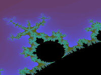
The fractals is a rough and fragmented geometric shape that can be split into parts, and each of which is a similar reduced-size copy of the whole. It is a geometric object that has self-similar structure and exhibits more and more details the more we zoom in.

The fractals was discovered by BenoƮt Mandelbrot in 1950s and the term "Fractals" was coined by him in 1975. For more than two thousand years since ancient Greek, people studied smooth behavior using equations that assume that everything evolves in a very regular fashion.
Somehow, Mandelbrot was attracted to the irregularities of the nature and studied phenomena that belong to very different organized sciences but have the common characteristic of being irregular and fragmented at many scales. Fractal examples in the nature include lightning, clouds, crystals, snow flakes, mountain ranges, river networks, coastlines, cauliflower, broccoli, etc.……


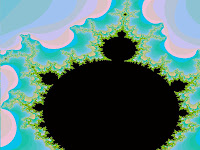
The most famous and well-studied fractal is the Mandelbrot set. Many Mandelbrot set zoom videos are available online, and here are some interesting examples: video 1, video 2, video 3, and video 4.

Students are encouraged to generated a series of Mandelbrot set zoom images (or even videos) based on the given C++ code. Here are some extra project-related resources which may help you implement the project:

[1] Mandelbrot Set Tutorial:

[2] PPM File Format Specification:

[3] Irfanview - Image Viewing and Format Conversion Software:

[4] Microsoft Visual C++ Development Environment:
http://www.microsoft.com/express/vc/

Student Fractals Project Photo Gallery (Precal 2009)


Friday, April 10, 2009

Precalculus Project - The World of Polypods


Story behind the project......


The polypod project was originated from a real-life engineering project almost 50 years ago. At that time, my dad was tackling an open challenge to build tetrapods for his company. Tetrapods are huge four-leg symmetrical concrete structure which are used to protect the seashore. (Tetrapods photos in Japan)

My dad used his high-school math training in geometry and trigonometry to solve the problem and build the tetrapods. After that project, due to his curiosity, he continued to research the topic and developed a series of polypods based on regular (also called Platonic Solid) and some semi-regular polyhedrons (also called Archimedean Solid).

Historical Polypod
The photo shows that I held a 32-tube polypod as my gift toy from my dad when I was very young. The polypod is based on the 32-face Icosidodecahedron. An icosidodecahedron is a polyhedron with twenty triangular faces and twelve pentagonal faces. (More information of Icosidodecahedron)

Polypod Photo Gallery

Here are some polypods examples which I built for the precalculus project in 2008.

I-Pod
- two tubes joint together with 45-degree cuts and form an I shape


Z-Pod
- three tubes joint together with 45-degree cuts and form a Z shape


Tripod
- Three tubes joint together with 120 degree between each pair of tubes


T-Pod
- Two tubes joint together to form T shape with 90 degree between them


Tetrapod
- Based on the Tetrahedron


Tri-Tpod
- A mutated version of Tetrapod with the top three tubes sitting on the same plane like a Tripod


Hexapod
- Based on the Hexahedron (Cube)


Octapod
- Based on the Octahedron


Dodecapod
- Based on the Dodecahedron


Isocapod
- Based on the Isocahedron


Student Polypod Project Photo Gallery (Precal 2008)


How to Build a Polypod?


The tetrapod will be used as an example to illustrate the steps of building a polypod.

[1] Calculate the "central angle" between any pair of the tubes. This angle is the supplementary angle of the "dihedral angle" of tetrapod. The dihedral angle and central angle can be calculated using basic geometry and trigonometry. (Example of central and dihedral angles calculation). The dihedral angle of tetrapod is 70.52877936 degrees, and the central angle is 109.47122064 degrees.

[2] Use planar unfolding skills to draft the unfolded diagram of the tube which will be cut at half of the central angle. An example of the unfolding diagram is shown in the following.


[3] Clean up the draft, copy & paste, and create a template for the Tetrapod. Cut and glue each tube, and then, tape them together to form a beautiful Tetrapod. Don't forget to leave some extra space for gluing. An example template of the Tetrapod is shown in the following.


The same steps can be used to build the polypods based on different polyhedrons.